802Projects
When I purchased the car, I knew it was due for the timing belt job. I actually preferred this as I like to do my own work to make sure it is done right. Shops are built on a "time is money" concept. They are not going to spend time cleaning parts. They likely will not look up torque specs or see what needs RTV and what doesn't. An impact driver is their best friend. If they run into a problem they are going to do whatever they can to rectify it as soon as possible. Maybe that means re-using an O-ring or installing an aftermarket bolt/clamp in your car that they had left over from a previous job. Maybe it means adding extra RTV or installing a timing cover with a missing seal as that part can't be "that important". The last thing they want is your car sitting apart on their lift while they wait for a part to come in.
This is why I encourage everyone to do their own work if you really care about your car. I always operate on the 2 step principle...
I'd rather invest in tools than to pay for potentially poor labor. Do as much homework as you can ahead of time. Make sure you have the OEM Service Manual. My car came with a physical book, but you can also find them online. By searching for "1991 Acura Nsx Service Manual PDF" I was able to find this one for a 1991 NSX. The online version is almost better as you can ctrl+F search to find the right page and torque specs vs flipping through pages. Then just take your time. Don't have friends over in the garage distracting you. Double check everything and get to it. The previous owner of my car had the timing belt service done by a shop that specialized in exotics. Despite that I still found several things that were not done right. Here were the major faults.
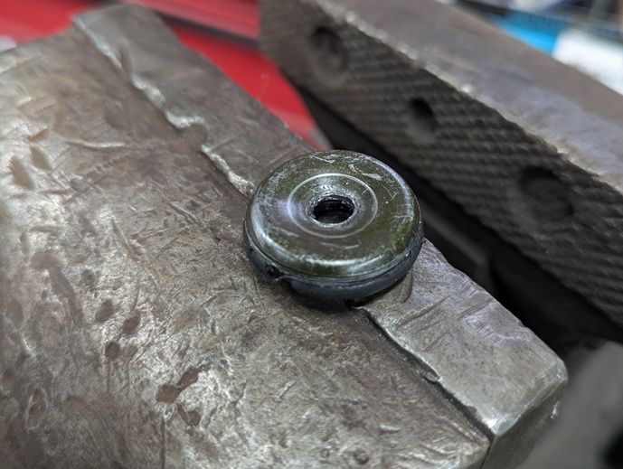
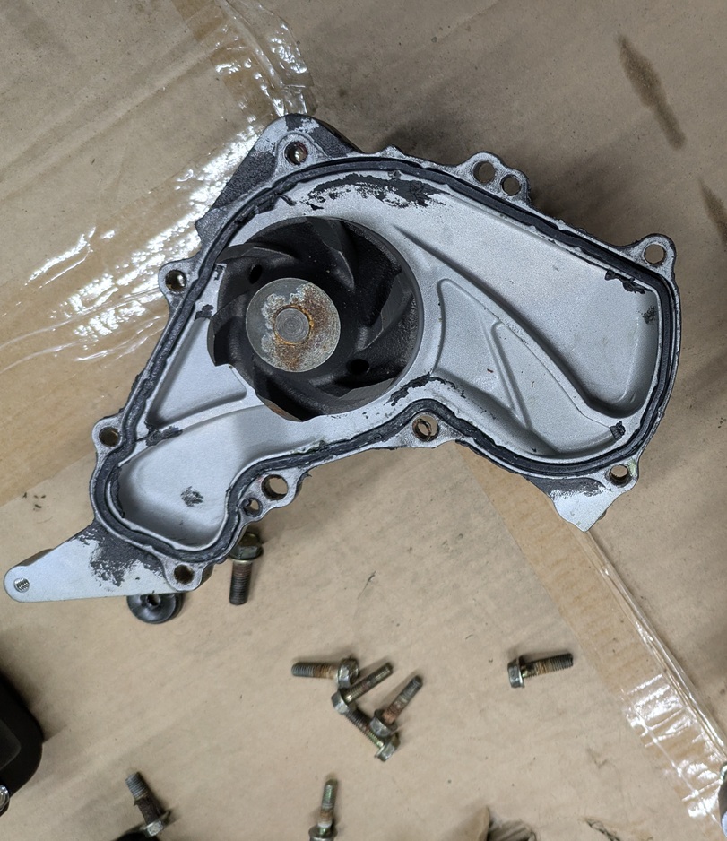
Now depending on how deep you want to go, your maintenance list could vary. My 1991 NSX had 33k miles on it. It is 2026 and the timing belt was last done in 2017. The coolant hoses were never replace per the previous owner. I opted to do both as "while you are in there items". I'm not going to do a step by step walk through, but I will reflect on what could be optional and explain why it makes sense to do certain things. I'll also go over some installation tips to make the job easier for you. When I list parts I'll include the current 2026 pricing to give you an idea on costs. I purchased the OEM parts all from OEMAcuraParts.com
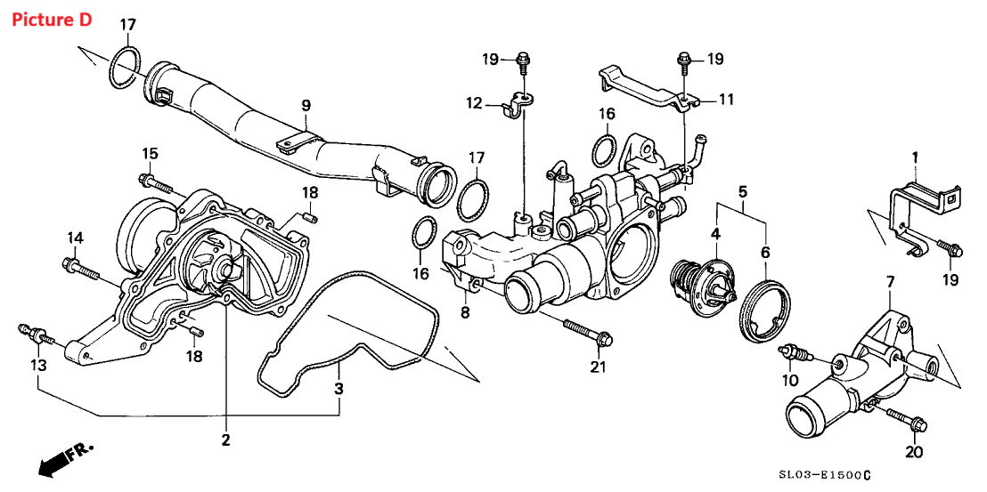
The NSX has more coolant hoses than a typical vehicle as it needs to carry coolant from the radiator at the front of the car, to the engine at the rear of the car. Two large coolant lines run under the vehicle (along with a 3rd medium size line) that are a combination of metal tubes and rubber hose sections. If one of these were to burst, it could be catastrophic for your engine. Seeing as my car lasted 35 years on the original hoses, I would probably recommend replacing these every 3 timing belt cycles. I opted to replace them all.
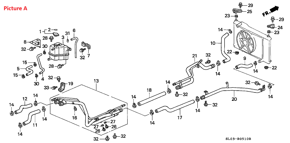
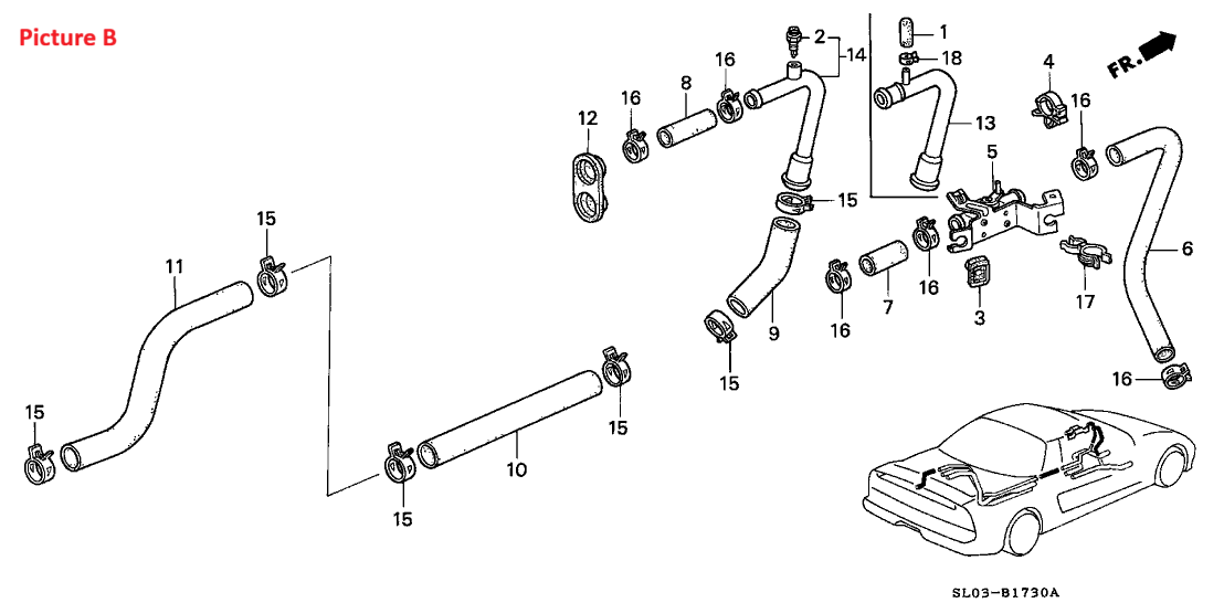
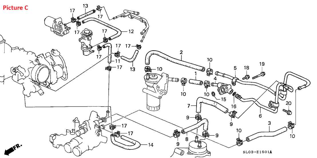
If you want to replace everything coolant, you can take it a step further and order more parts. There are some O-rings in the water pipe that runs across the center of the block and in the thermostat housing. Getting to some of these will require the intake manifold to come off. I was already taking that off to do the IAB delete so it made sense to do these now. Be careful when pulling the water pipe. The factory knock sensor wiring and knock sensors are all right there in the way. Everything in the center of the engine gets brittle from heat. I ended up shattering the plastic on one of my knock sensors just trying to unplug it. I also broke the plastic tray that holds the knock sensor wiring in. That was an expensive mistake. (Factory Knock Sensor part# 30530-PR7-A01, Plastic tray part# 30532-PR7-A01. I ended up ordering two new knock sensors for $380 from Amayama and a $60 tray from OEMAcuraParts.com)
When doing coolant hoses you will definitely want a good set of hose clamps. The cable tool is a must. I was not able to twist off a lot of my hoses. I had to carefully cut them off. I found sticking a 90 degree pick in the end and pulling the rubber away while cutting with a razor blade worked best as it helped prevent scoring the pipe. When installing new hoses, I used some silicone spray to help slide them on.
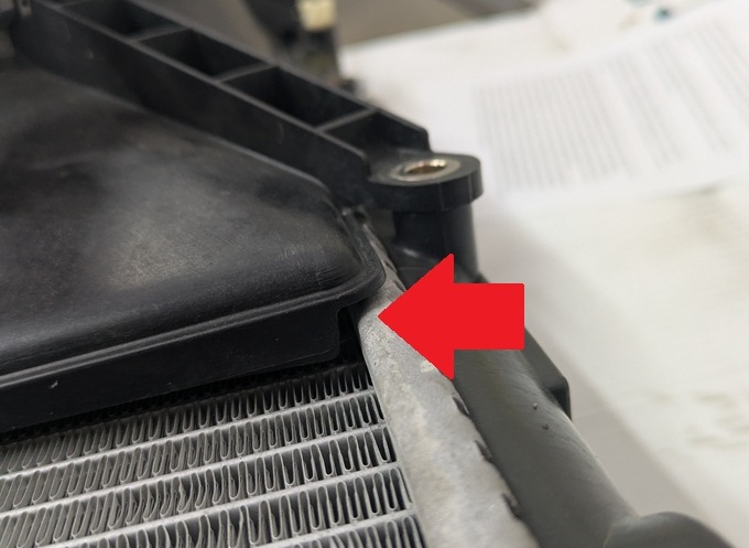
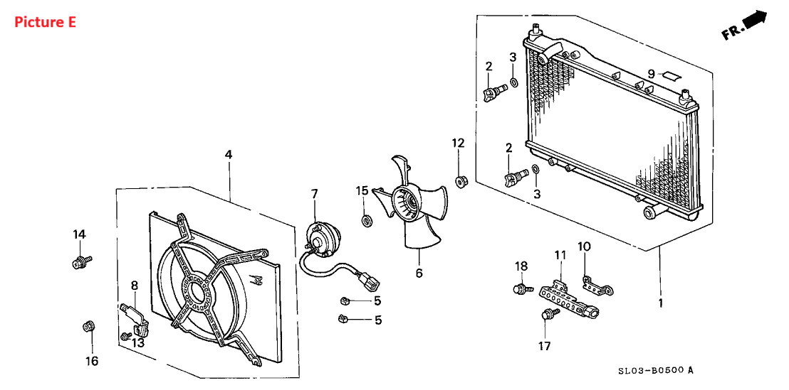
I wasn't planning on replacing my radiator, but when I got the original one out... it just looked beat up. Despite having trouble with Koyo in the past (leaking Subaru radiator), I opted for them over Mishimoto as I was told it was a direct fit and the Mishimoto needed modifications. The Koyo is not a direct fit. The studs for the fan shroud stick out further than the factory radiator. This causes the fan shroud to not sit flush against the radiator. This puts the edges of the fan shroud further away from the radiator and closer to hitting the angled inlet/outlet pipes. When you slide the hose and clamp on, these pipes become thicker and the shroud will hit. You need to notch two half moon shapes into the shroud. I also had to slightly enlarge one of the factory radiator brackets to make it align better with one of the pins on top of the Koyo. Hindsight I wish I went with Mishimoto as they likely need the same work and at least have a better warranty. Whoever said these are direct fit either A) Shoved the shroud on and its got a lot of tension on it B) Doesn't consider taking a Dremel to a fan shroud a modification or 3) Maybe has their coolant hoses not shoved on far enough and the clamp is sitting on top of the flare vs beyond it.
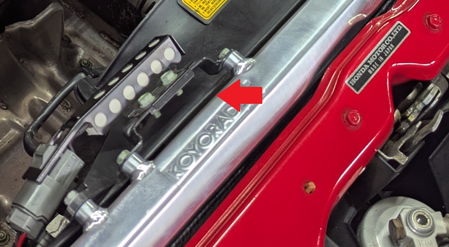
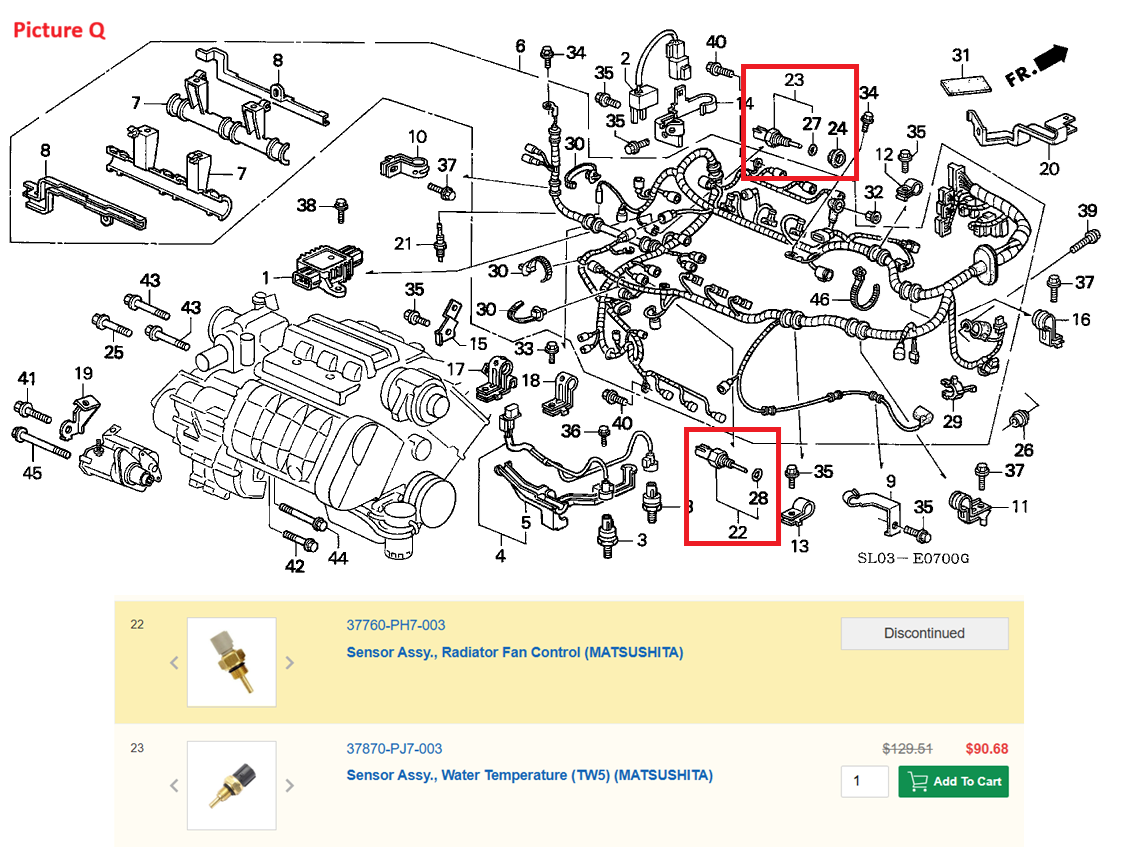
There are 3 coolant temp sensors on the NSX: 1) ECU Sensor, 2) Dash Gauge Sensor, and 3) Radiator Fan sensor. The ECU sensor is on the driver side of the front head. It is directly below the EGR tube area and recessed quite a bit. The socket flange area also has a rubber cover that you need to remove to fit a 19mm deep socket on it. The rubber cover is going to be dried up and it will 100% crack and fall off when you try to remove it. It's also discontinued and hopefully not too important. This sensor does have an O-ring. The dash gauge sensor points straight up on the rear part of the thermostat housing. It has a single wire going to it and has a straight pin like connector. This sensor DOES NOT have an O-ring. It uses a little Honda Bond on the threads. I would avoid doing anything with this sensor unless it is leaking or has issues. The radiator fan sensor (22mm deep socket to remove, no rubber cover) is also on the thermostat housing. It points towards the driver side and is below the throttle body. This has an O-Ring. I replaced both O-Rings on my sensors as they were 30 years old, but honestly they looked fine. I'd imagine your sensor will probably fail before an O-Ring does and when you buy a new sensor; it will come with the O-Ring. I'd probably skip these if I did it again as my sensors worked and didn't leak. However for $5 in O-rings and 10 minutes of work, I don't necessarily regret doing them.
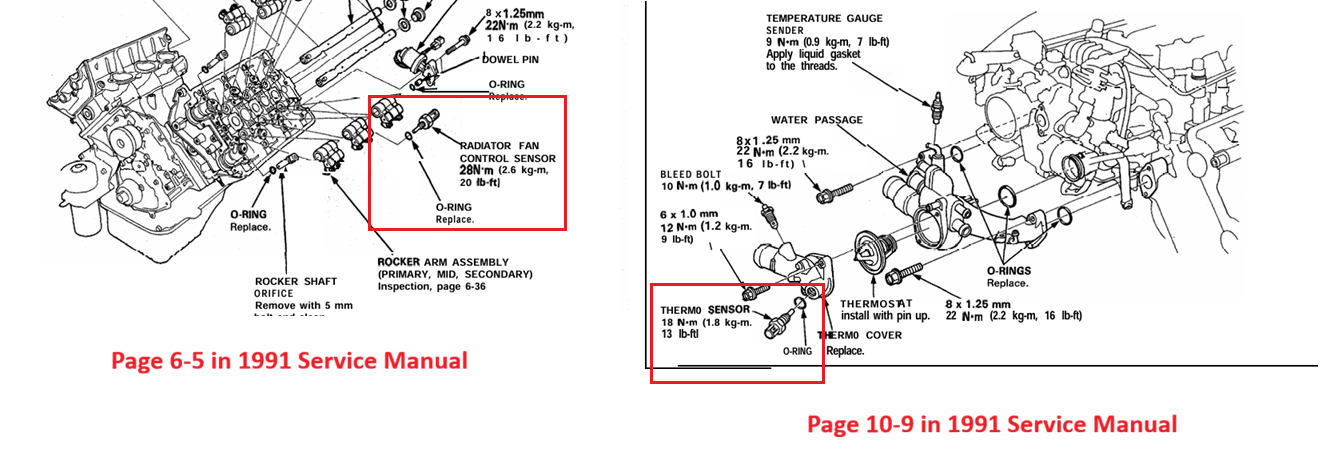
Also the part descriptions can be a little confusing when comparing the service manual to the online part diagrams for ordering. I just called the sensor on the thermostat housing the "radiator fan" sensor. I did this because when you look at the online part diagrams, the sensor (Part# 37760-PH7-00 which is #22 in Picture Q) is called "Sensor Assy., Radiator Fan Control (MATSUSHITA)". The other sensor (Part# 37870-PJ7-003 which must be #23 in Picture Q as #24 is the rubber cover) on the front head is called "Sensor Assy., Water Temperature (TW5) (MATSUSHITA)". But when you look at the service manual pages 6-5 and 10-9 they have the names switched. They call the sensor in the head the "Radiator Fan Control Sensor". Someone is obviously wrong. Regardless, I list the part numbers in reference to location. I torqued the sensor in the rear head to 20 ft/lbs and the sensor in the thermostat housing to 13 ft/lbs.
If you have a 1991, check your frunk for the upper heater core line. Does the metal elbow coming off it have a brake bleeder type valve on top or does it have a rubber cap clamped onto it? Early cars have a rubber cap. If you want to upgrade to the revised pipe with the valve, below is the part#. I opted to do this. I figure it's one less failure point. If you want to keep the rubber cap, a new one is only about $10 (part# 19515-PH4-600) and I'd recommend replacing it at the same interval you do the hoses at.
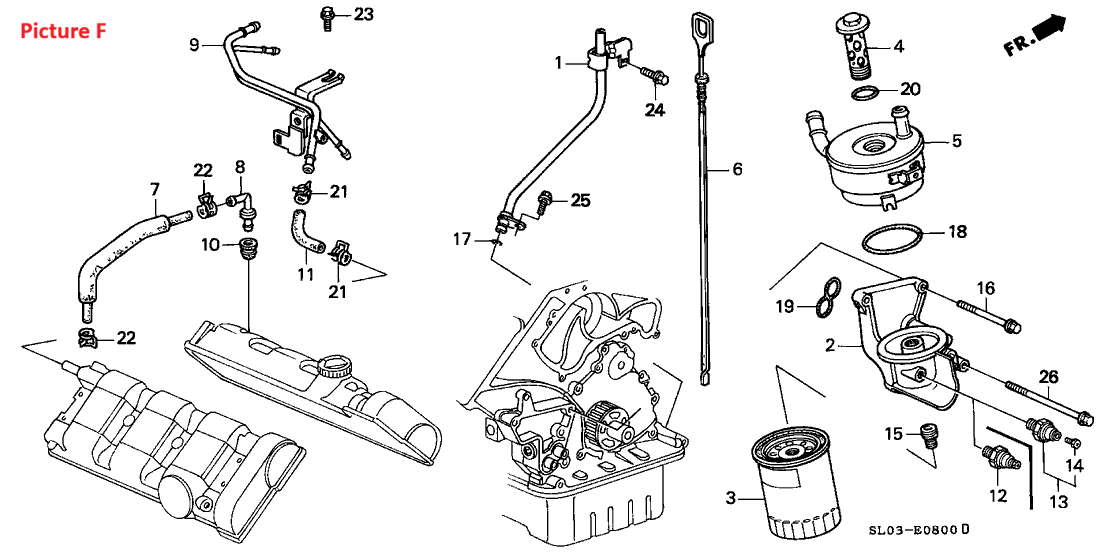
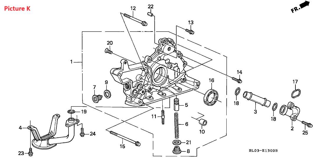
To replace the two coolant hoses that run to the oil cooler; it needs to come off. The OEM factory service manual also wants you to unbolt it and pull it out of the way to get to one of the timing cover bolts. I pulled mine off and rebuilt it. The minimum to get by here would be to order just the figure 8 seal. The manual says the top two mounting bolts should be replaced as well as they contain a sealant on the threads, but some people apply their own thread sealer. There is also a 3rd longer bolt, but that doesn't thread into anything with oil behind it so I re-used mine. The manual didn't call for the longer bolt to be replaced. Inside the oil cooler are some O-rings. Since it's off, now would be the time to replace them. I feel most people skip this step, but it may be that they are unaware they are rebuildable. Now would be the time to replace $12 in extra O-rings. Assuming you are changing your oil too, I am including part# for OEM oil filter and crush washers for drain bolt.
I would recommend going with OEM parts for the main timing belt stuff. This is not something you want to cheap out on as the NSX is an interference motor. If you want to save some money, you could go with an aftermarket Alternator and A/C belt. You could also skip replacing them if your belts are fine. I could see you also skipping the water pump every other timing cycle if it is not leaking.
A long time ago the weep location for the water pump was BEHIND the lower timing belt cover. So if your water pump started failing, it would drip coolant out onto your timing belt where it would splash around hidden behind the covers. This could prolong you noticing a leak. Honda revised the water pump in the early 90s. Now it has a weep tube that sticks through the lower timing cover. When you buy a new OEM water pump it is going to come with a revised lower timing cover (part# 11810-PR7-A02) which has a small hole for this weep tube. It will also come with a new weep tube grommet (part# 11816-PR7-000). However the lower timing cover they include WILL NOT come with a lower cover seal (part# 11841-PR7-A00). They expect you to transfer it from the old cover. Many times this step gets missed and your lower cover gets installed without this seal. Look closely where the upper timing covers meet the lower timing cover. In that seam do you see any kind of rubber? If so it means you have the seal. If not, it is missing.
Also if you already have the revised water pump on your car (easy to check as you can look down at your lower timing cover and see if you have a metal weep tube sticking out it), you may be asking if you can just get the water pump and save money? The answer is no. I think there is a part# for just the water pump, but it's the same price as the combo. So just buy the combo.
The Service Manual will have you remove the spark plugs too so you are not fighting compression when spinning the crank by hand. Now would be a good time to replace them. I went with NGK 5555 from RockAuto. They come pre-gapped, but it's a good idea to double check them. RockAuto sells them individually or in 4 packs. It was cheapest to buy one 4 pack and 2 individuals.
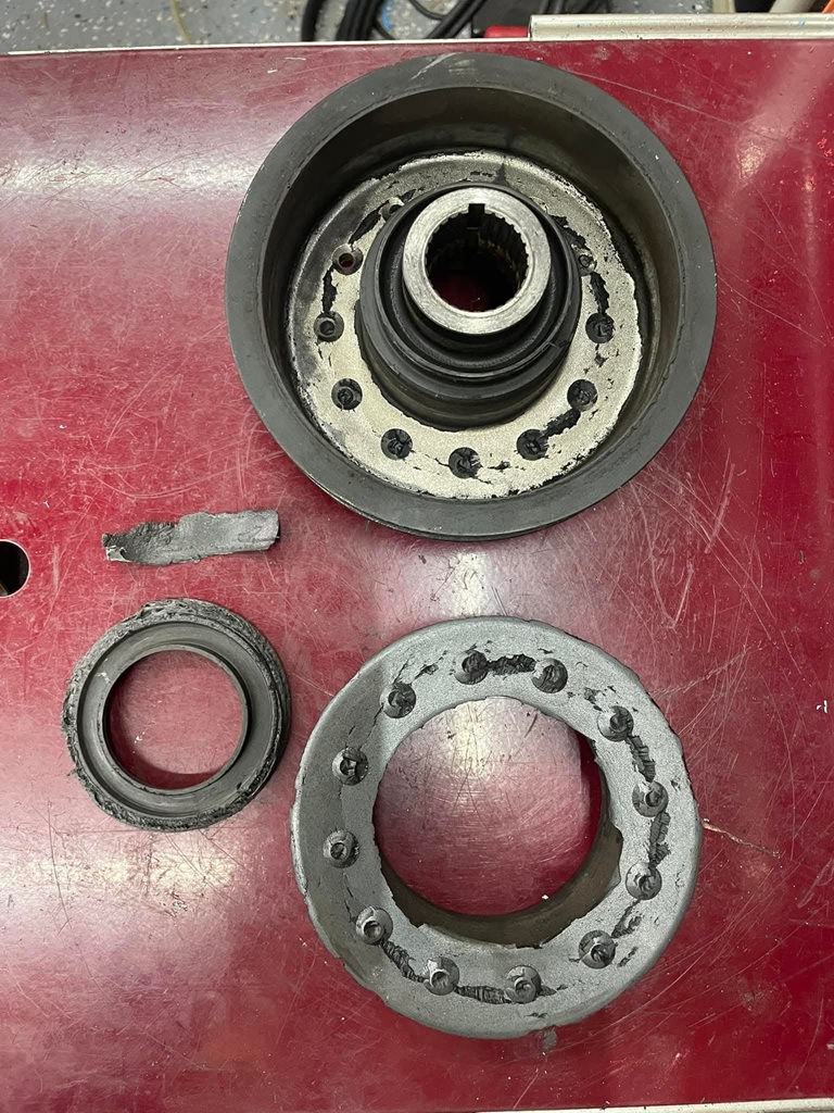
The OEM Crank Pulley is known to fail. Over time the rubber holding the two halves together breaks down and it separates. The inner half has no where to go so it just spins and wobbles against the lower timing cover. In a short time it can wear through the cover and into your timing belt. Best case you notice it in time. Worst case it takes out your motor. Here are some photos I found online of a failure caught just in time.
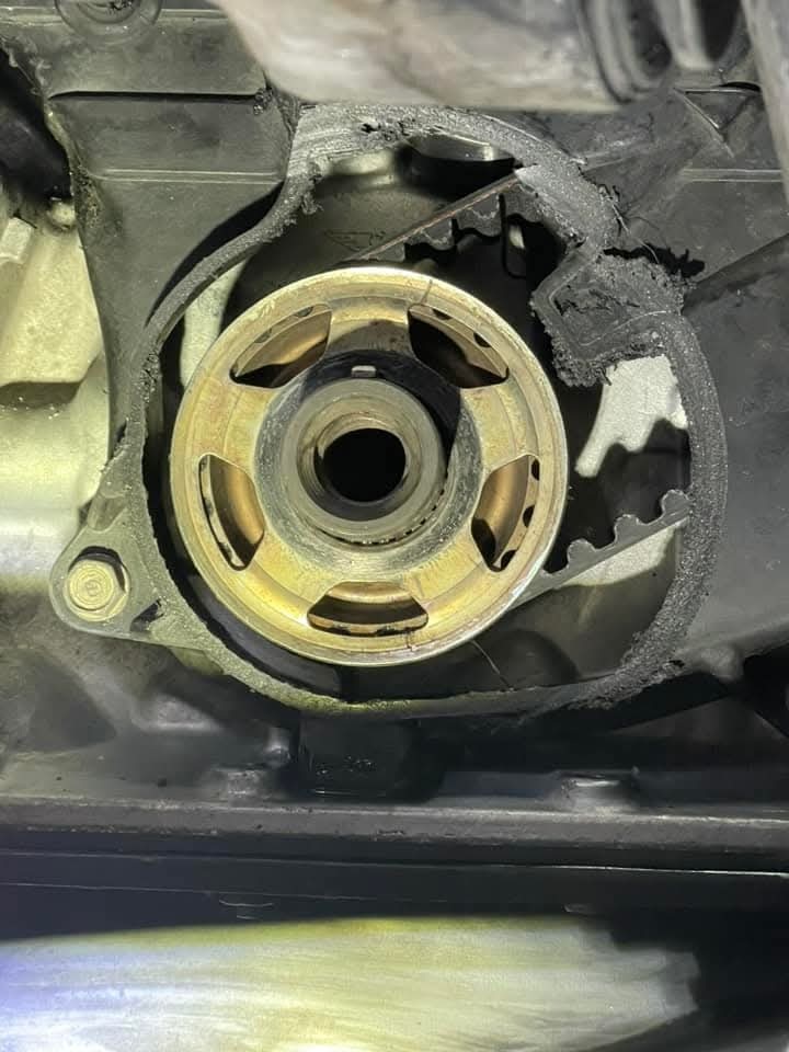
I would not re-use an OEM Crank Pulley. For people who want to stay OEM, I'd recommend getting a new one every timing belt job. Cedar Ridge also makes a metal backing plate you can install behind the pulley and in front of your timing cover. If the pulley was to separate, the plate would buy you some time and maybe save your belt.
I like to eliminate risk whenever possible, so I went with an aftermarket pulley (ATI Super Damper ATI-917757 from Jegs). The ATI Pulley will not separate, but it does have some big O-rings inside that are supposed to be replaced based on usage. For me that means rebuilding it every 10 years. I wish Fluidampr made Crank Pulleys for our cars. Those are easy to install like the OEM pulley and have no maintenance. If your platform has the choice between Fluidampr and ATI, I'd go with Fluidampr every time. The ATI Super Damper is also interference fit which makes it more of a pain to install. You need to press it onto your crank. You are also supposed to measure it with a micrometer to make sure it is within spec and does not require boring before use. However the install instructions contradict themselves and say if you have a factory installed crank the tolerance is 99.99% always correct. The measuring part is intended mostly for aftermarket crankshafts.
To install it properly you need a special tool. ATI sells one (Part# ATI-918999) which is around $240. Fortunately my friend already had the tool and let me borrow it. If I had to purchase the tool myself, I would have looked into some of the cheaper knock off kits. Harbor Freight even has one now. The ATI kit will not come with the right threaded adapter for the Honda Crank as that would be too convenient. RelentlessRacing sells an adapter (M16x1.5 for the Honda Crank and 1/2-20 for the ATI tool) for $60. PrecisionPerformance also makes one for a little less, but their website was not as friendly.
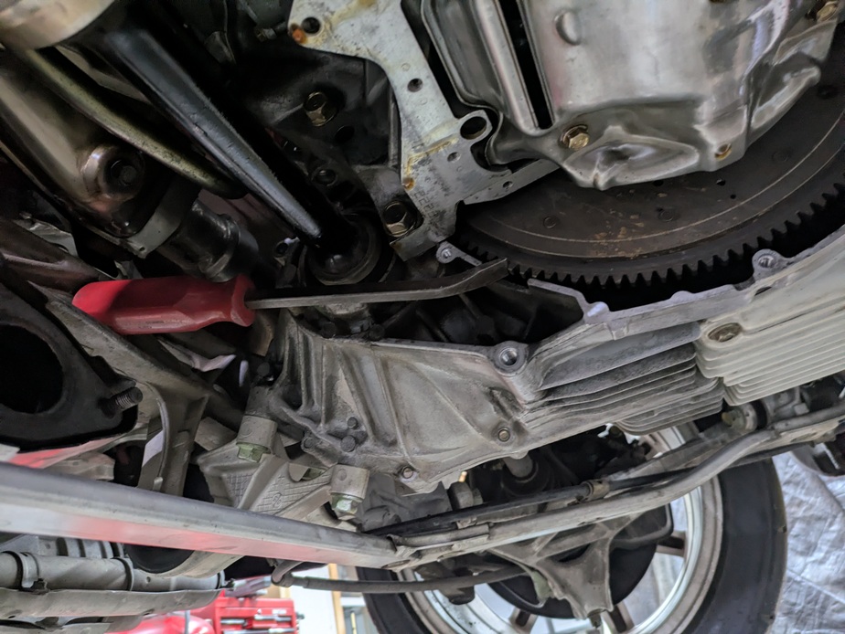
When you install the crank pulley you will remove the three 5/16 accessory pulley bolts so the install tool plate can sit flat against it. Definitely do the XYZ measurements in the instructions so you will know 100% when it is seated fully. My X measurement was 16.93mm, and my Y measurement was 29.30mm. This means my Z measurement was 13.37mm. Make sure the key is seated and lined up. I'd start pressing it in with the tool, then stop after a few turns, remove the center shaft so you can visually inspect the key, then keep going. As you turn the big nut on the tool to pull the damper in, the crank will want to spin. You are supposed to use a big adjustable wrench and then apply force the other way using a 19mm socket on the end of the tool. This keeps the motor from wanting to spin. There is not a lot of space to work with trying to juggle a big adjustable and 19mm wrench with opposing forces. I found that a small Craftsman prybar fit perfectly between the subframe and flywheel (See Pic. I had the oil pan off, not sure if it would fit with the pan on or not if you just remove the inspection plate). This kept the engine from spinning and I could ditch the 19mm wrench. Then I used a 27mm deep socket and ditched the big adjustable. After it is pressed in you should re-install the three 5/16 pulley bolts with blue loc-tite and torque them to 16 ft-lbs. The other torx bolts on the pulley you should not need to touch. However if you ever rebuilt it in the future or wanted to double check the torque on them, you will need a T40+ (PLUS) torx bit. It is different than the standard T40 bit as the gear teeth are wider. RelentlessRacing sells the bit in this pulley removal package, so I grabbed one when ordering the adapter. After the bolts are torqued, you can re-install the crank bolt, torque it to 181 ft-lbs and remove the prybar.
The ATI Instructions recommend a new Crank Pulley Bolt, but why wouldn't they? Mine looked perfectly fine and it's expensive so I re-used it. Sandwiching the crank gear are 2 timing belt guide plates. The outer one must go on BEFORE the lower timing cover. The diameter of the plate is bigger than the hole in the cover. If a previous installer didn't realize this in time, they may have purposely "lost" the outer plate and you will want to buy a replacement.
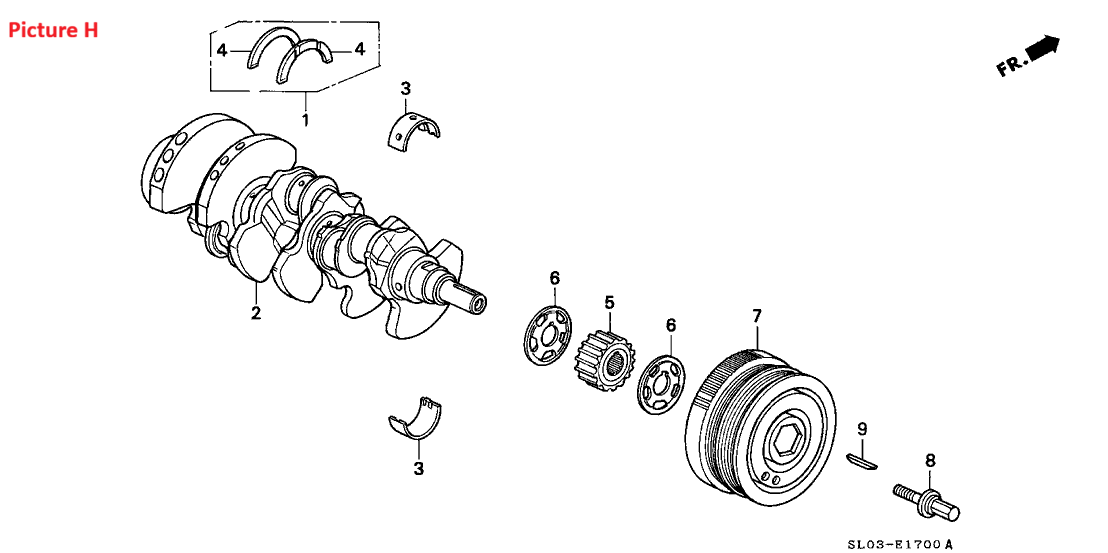
The factory service manual calls for replacing the water pump bolts as they have a special sealant on the end. You could probably re-use them if you applied your own sealant. I replaced mine. There are also 2 factory dowel pins that press into the block. Sometimes these pull out stay stuck to the old water pump. This may go unnoticed and yours could be missing. On my car 1 was missing. They are only a few dollars so I opted to buy them ahead of time. I'm glad I did.
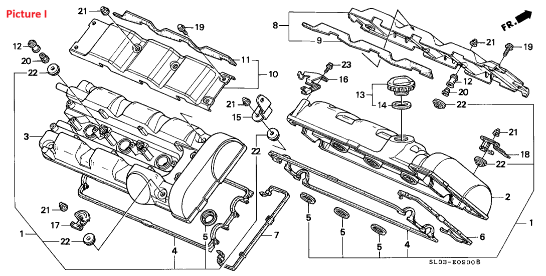
In order to do the timing belt, the valve covers need to come off. Unless you recently had the covers off for something else and just replaced the seals; I would not try to re-use them. HondaBond is required for the corner areas around the cam/caps so I'm including a tube of that. The service manual also calls for putting some between the covers and the seals to keep them from falling out when you go to reinstall the valve covers. I added a tiny drop of HondaBond about every inch before pressing the seal in.
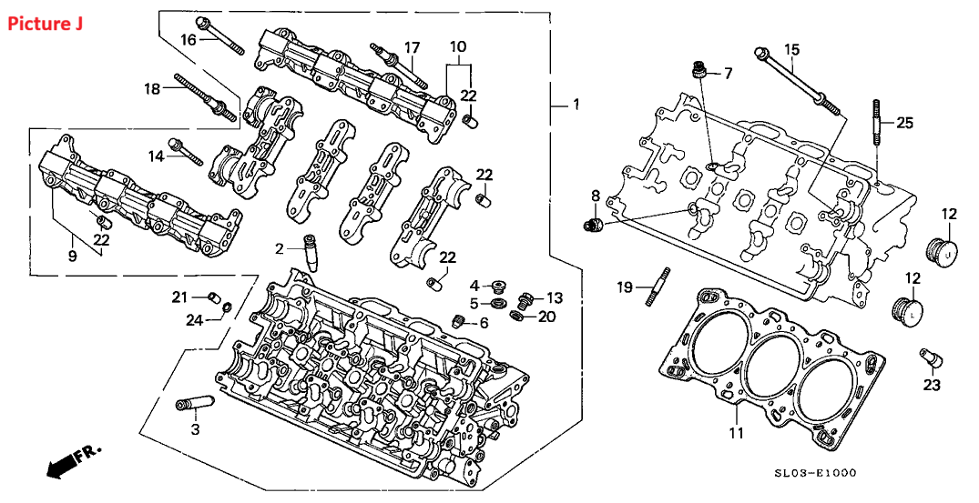
It is very common for the factory cam plugs (opposite the cam seals) to leak. It is so common that people have tried to find clever ways to replace the plugs without touching anything else. The plugs have an inner lip on them so even if you remove the end caps, you cannot slide a new plug in (or the old plug out) as the camshaft would be in the way. Some people have has success loosening all the caps and tilting just the drivers side of the camshafts up slightly in order to slide the plug in/out. People do this to fix a leak and avoid touching their timing stuff. But this page is about doing the timing belt job, so we are going to end up removing the camshafts to replace the plugs and cam seals. I went with Science of Speed billet plugs which use Viton O-rings. These are easier to install and next time around I can re-use them.
When you remove the cam caps closest to the cam gears, there is an oil passage underneath. In the center is a hollow dowel pin that has an O-ring around it (#21 and #24 in Picture J). Be careful this doesn't fall out when pulling the caps off. Usually it comes off with the cap. You will want to remove it and push it back onto the top of the head with a new O-ring. This way gravity isn't working against you when you go to reinstall everything. It just so happens that the dip stick tube (which you should remove to make taking the timing covers off easier), uses the same O-ring. That is why there are 3 of them listed.
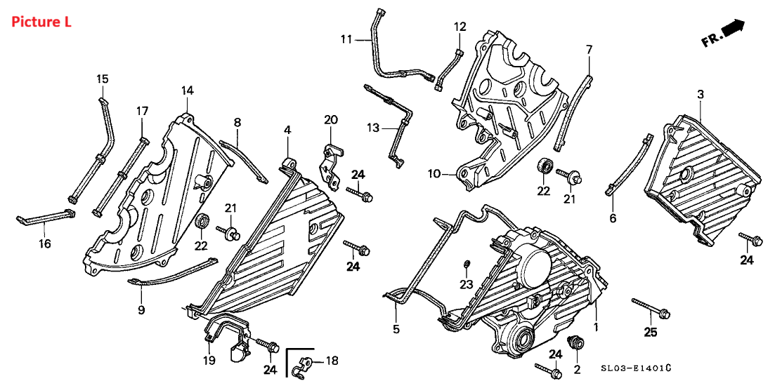
Behind your factory timing covers are rubber sealing gaskets. Technically two of them go underneath the timing belt area of your valve covers. Now my car is 35 years old with 33k miles and all of these gaskets seemed re-usable. They were not dried up or cracking. Aside for the one that was missing on my lower timing cover, I could have easily re-used all of these. However I had already purchased new ones ahead of time so I replaced them. I'll re-evaluate in another 30 years. I re-used my plastic timing covers, but if yours are beat up and you want them to match the new condition of the lower cover that comes with the water pump; I included them as optional at the bottom of the list.
The VTEC rocker arms need support when they are not in use. Otherwise they would rattle around. From the factory, Honda used hydraulic pistons to achieve this. Over time these pistons get sticky which can cause your valvetrain to be noisy. Honda switched to a spring system around 1999. These newer springs were not a direct fit in earlier year motors. I believe they were too short. They eventually created some that were the right size (part# 14820-PCB-305). I believe in the interim SOS (Science of Speed) created their own product as well. I'm not certain if they had everything manufactured from scratch, or if they simply use the shorter 1999+ springs and install taller spacers. I opted to just go with the OEM Honda part, but plenty of people use SOS. I found this compare thread on another Honda Forum which helped in my decision:
https://honda-tech.com/forums/engine-machining-assembly-164/oem-vs-skunk2-vs-sos-b-series-lma-comparison-test-3250651/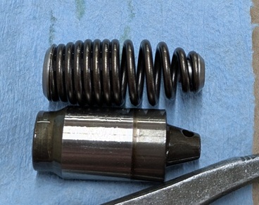
When you install the LMAs the rocker shafts need to slide out. The VTEC Solenoids are in the way so they need to be removed. Each solenoid contains 2 different seals, but technically you only need to expose one of them. The side seal (part# 15825-PR3-005) that attaches the solenoid to the head will need to be replaced. The top seal you could skip as you don't need to take it apart and they are not difficult to access down the road. I replaced mine because what is an extra $46? There are four 55mm torx plugs (1 for each shaft) on the end of the head you need to remove. These have crush washers behind them you need to replace. The rocker shafts are pinned by four little plugs (1 for each shaft) in the head towards the cam gear side. In order to remove them you need to thread in a M5x0.8 bolt then pull them out. Each plug has a little O-ring that will need to be replaced.
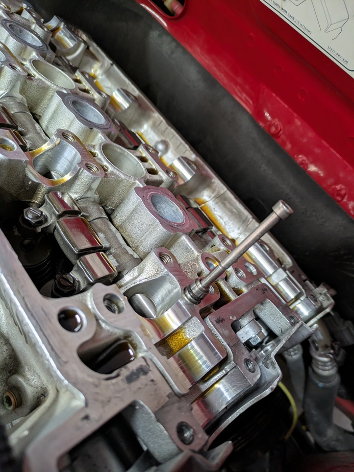
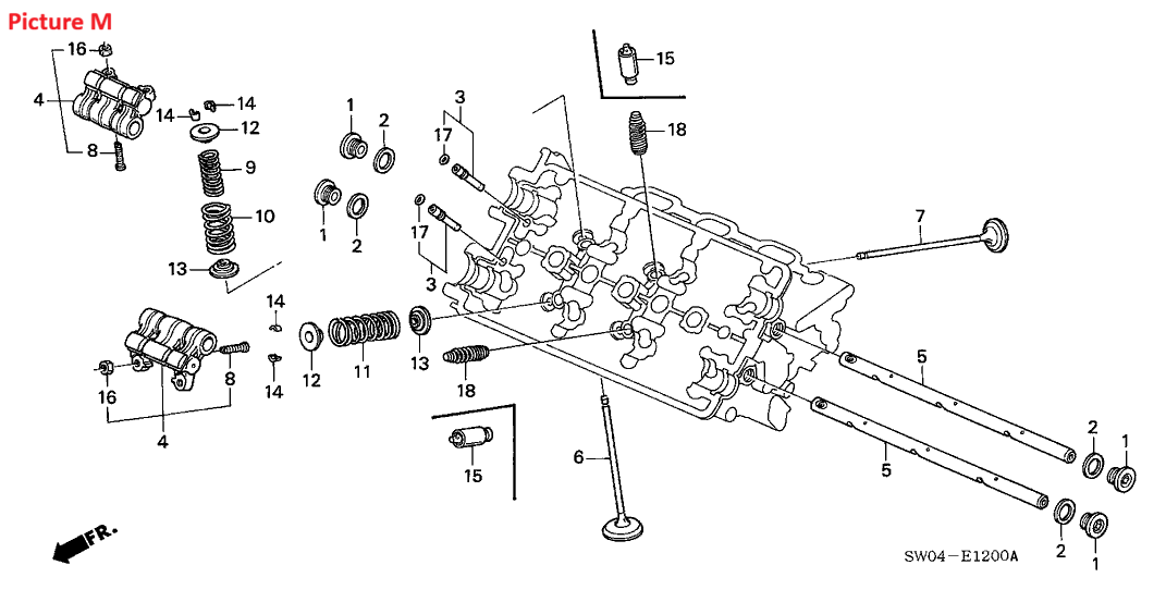
Now there are several things you need to do before you slide the shafts out. Get some pliers ready as you'll need them when pulling out the old hydraulic pistons. The front most rocker shaft will hit one of the big coolant hoses as you slide it out. If you are removing your coolant hoses anyways, do that beforehand. If your hoses are still present, I'm not sure if you could squeeze/push the hose out of the way or not. The rear most shaft will hit the plastic cylinder thing underneath the fuse box. You should unbolt the fuse box (two bolts) so it can be lifted out of the way. You will need a M12x1.5 bolt to thread into each shaft to give you something to pull on. Get that ready. Then finally you need to bind the rockers together with rubber bands. I recommend getting the $3 rubber band pack from Harbor Freight. There are several sizes inside, but just pull out the green ones. Not all the green rubber bands are made equal. If any have skinny sections, toss those aside. You want 3 per bank. The oil will start to break down the rubber so I wouldn't re-use them and you want to work at a steady pace. Don't put them on, then go make a sandwich. Pick a shaft, install the bands, slide it out and carefully pull the rocker banks off as you go and set them aside. The rubber bands will keep them together and prevent any pistons inside them from falling out. You don't need to remove the shaft entirely, just far enough to get the last rocker bank off. Then swap in the springs and slide everything back together. After a rocker bank is back on, I'd remove the rubber bands from it and go to the next one. The last thing you want is a rubber band to snap and go who knows where.
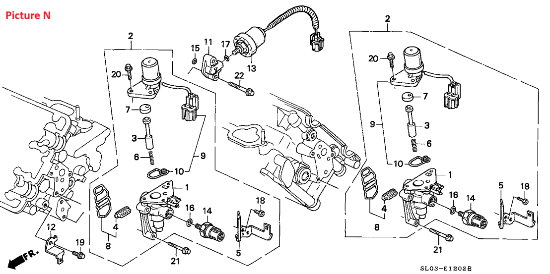
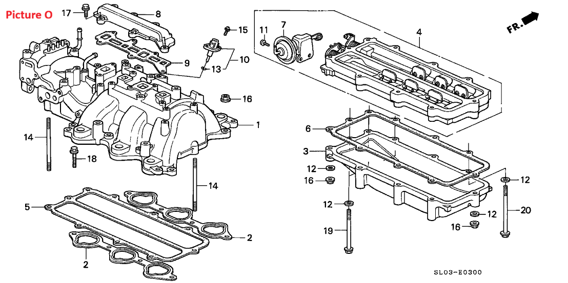
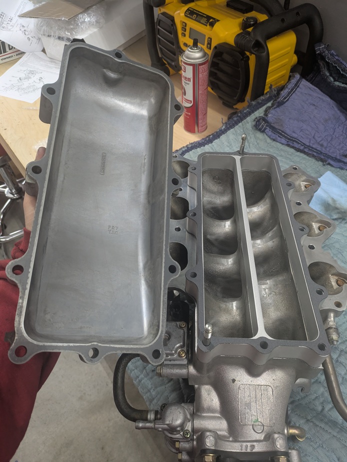
Inside the intake are 6 butterfly valves. The plates are each held in with 2 mini screw bolts. Over time these have been known to vibrate loose and fall out into the engine. The purpose behind this is to provide slightly more low end torque. I would argue it also hurts top end. To me this is not worth the trade off for the safety of your engine. SOS makes an IAB delete kit that I purchased. The intake does need to come out to install it. If you choose to keep your IAB system you should at least inspect it using a scope through the throttle body. I had inspected mine and everything was fine. However you may not know if something is loose before it is too late. The SOS kit comes with all new gaskets EXCEPT the lower manifold ones. People tend to clean and re-use them as they are expensive which is what I did. However I'm including the part# in case you need it.
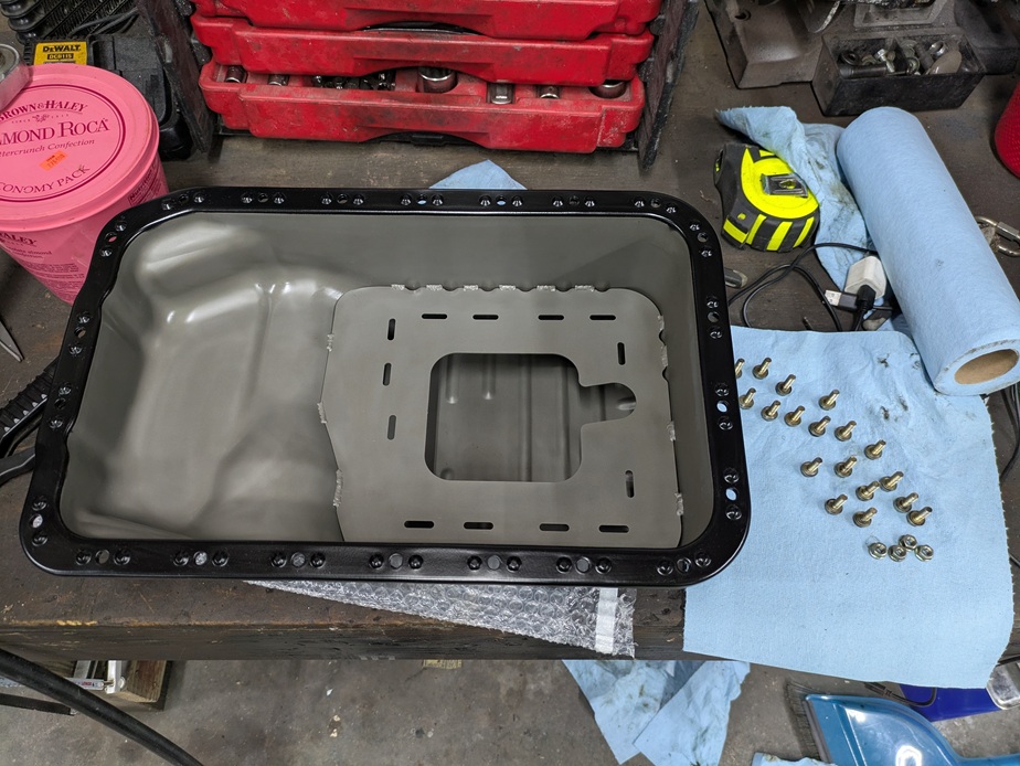
The factory oil pan is unlike other 90s sports cars I have owned. It does not contain any baffles to keep the oil around the pickup tube on long sweeping turns. This could starve the engine of oil. It also seals using a rubber gasket which is prone to leaking if not done right. As part of the maintenance work I wanted to address the lack of a baffle. There are a few different companies that make weld in baffles. I opted to go with the one from Cedar Ridge. Fortunately they offer an install service and will even powder coat the pan. The only thing that I'm not 100% happy about is that they now leave the inside of the pan bare. Originally they would powder coat the inside too, but stopped sometime in 2023 over fear the powder coat would chip off and clog the pickup. I agree with their reasoning and that the oil sloshing around the pan should keep it from rusting... It just bugs me a little as the pans were coated black on the inside from the factory. Another pan I considered was the RFY cast aluminum pan from Japan, but I understand this is hard to get. Plus they are over $1000 after import fees and shipping.
While the pan is off you should inspect the pickup tube. Shine a light inside, and you'll likely see some stuff stuck (ie small rtv pieces, maybe hair, shop towel fiber etc) on the screen. I spent an hour carefully cleaning it with a small pick and a can of brake cleaner to help wash it out. Compressed air also helps blow stuff off the screen. When re-installing the pan the seal should go on dry with the exception of a little Honda Bond in 4 spots where the 2 seams are (Seam 1: between the block and oil pump, Seam 2:between the block and rear main housing). Apply the sealant to those areas directly to the underside of the block. No sealant goes between the gasket and the pan.
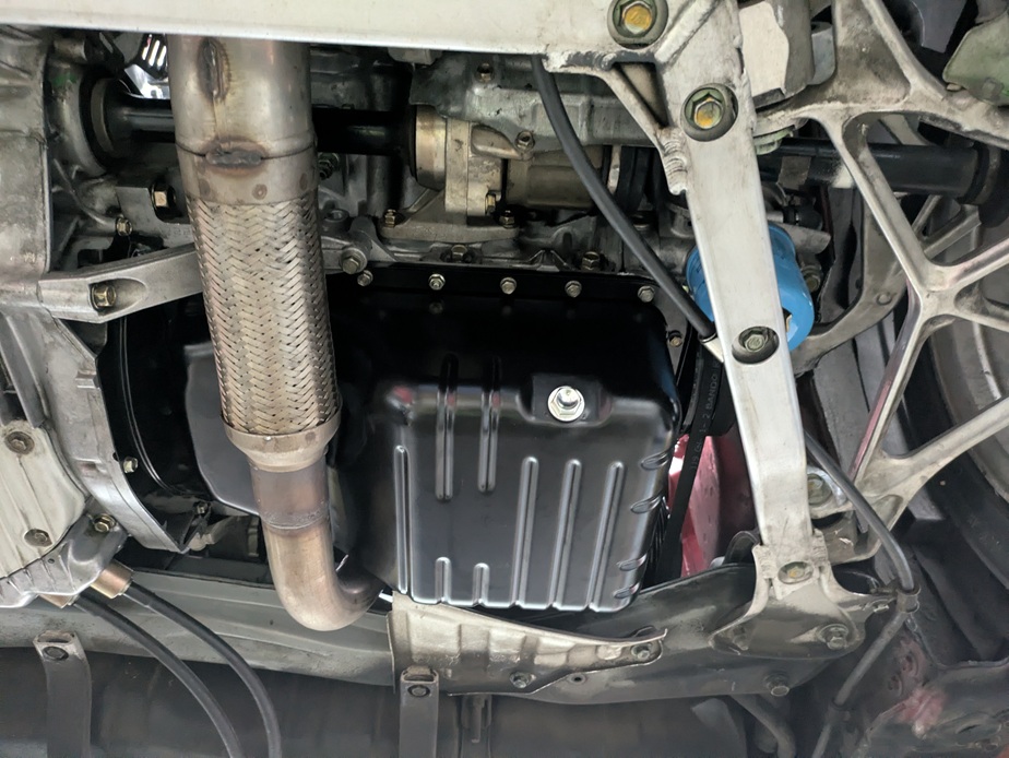
To get to the pan your adventure may vary based on what exhaust you have. It's easiest on the 1991-1996 with the factory exhaust. There is a joint below the front header and another one right before the cat. Remove 6 nuts and you have open access to the pan. On later years and with a lot of aftermarket exhausts, the front header has to come off. Mine is a 1991 with an oem exhaust, so that is what I'm listing for gaskets in my parts list. If your exhaust differs, then you will have some homework to do. I had 2 exhaust nuts come off hard, so I bought all new nuts and I cleaned up the studs using a tap and die kit.
The pan on my car had been off before. Whoever installed it used a very strong sealant around both sides of the entire factory gasket. It took over an hour to break the seal with a small putty knife. Then cleaning up the residue took even longer as nothing wanted to break it down. Whatever they used was much stronger than RTV. Before tackling this project I had considered using RTV myself, but this mess convinced me not to.
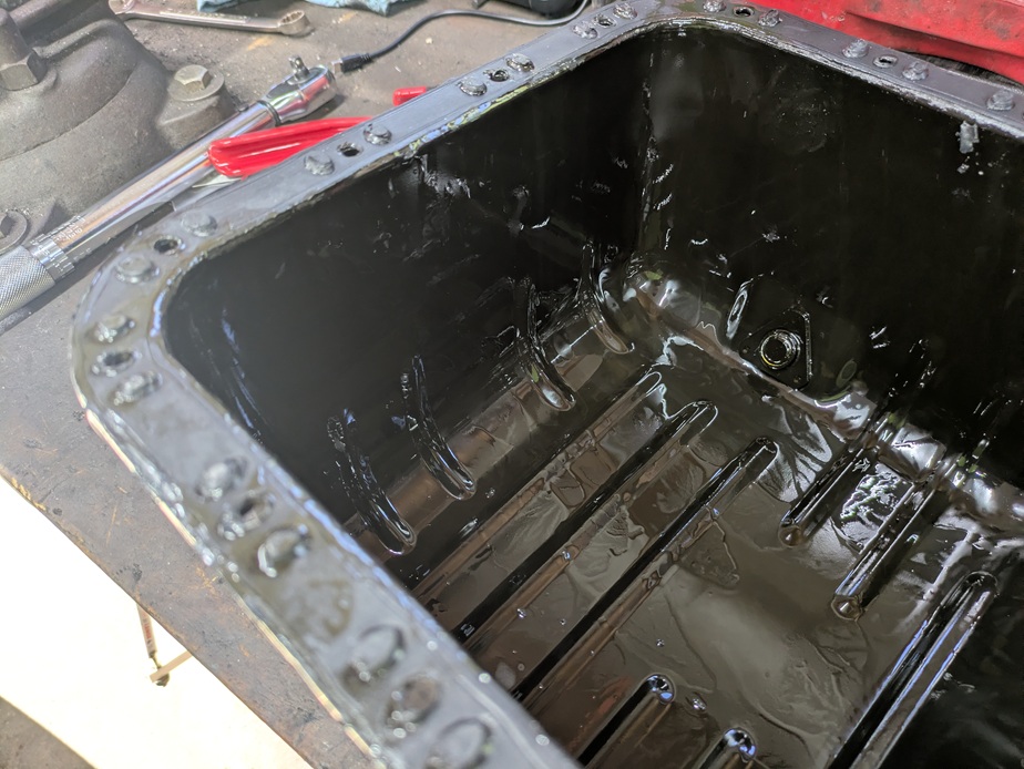
My pan arrived at Cedar Ridge on a Monday. Seven days later I had a tracking number for return shipping. Unfortunately it took another 7 days to arrive as they are in Oregon and I'm in Vermont. So plan accordingly. I am very satisfied with the weld and powder coat job.
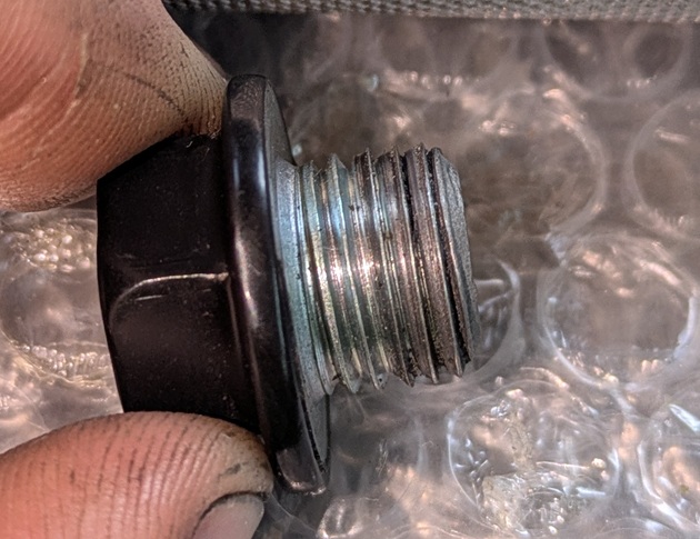
One thing I do wish I inspected better before sending the pan out is the drain plug. Only owning the car for a short while, I had never changed the oil in it. I drained the oil, cleaned the pan and sent it out. My drain bolt didn't want to thread back in easy and it looked like it was going in at an angle. On closer inspection the threads were messed up (fortunately just on the plug itself and not the pan). I had an extra plug from a 3000gt with good threads that I tried. I could thread that in by hand, but it was still going in at an angle. Nothing looked cross threaded and it held torque fine; it was just cockeyed. I probably could have left it as-is, but I was worried it wouldn't make a good seal even with the crush washer. One side would hit and the other side may not crush down very much. So I risked threading in a bolt and giving it some very light taps with a hammer. Everything is square now and it seals fine. Hindsight you should inspect the drain plug before sending your pan out. Make sure the drain bolt isn't stretched from over tightening. Make sure it threads in straight and holds torque. Make any adjustments ahead of time.
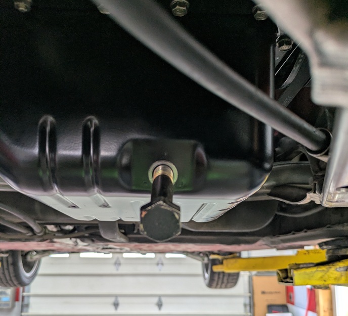
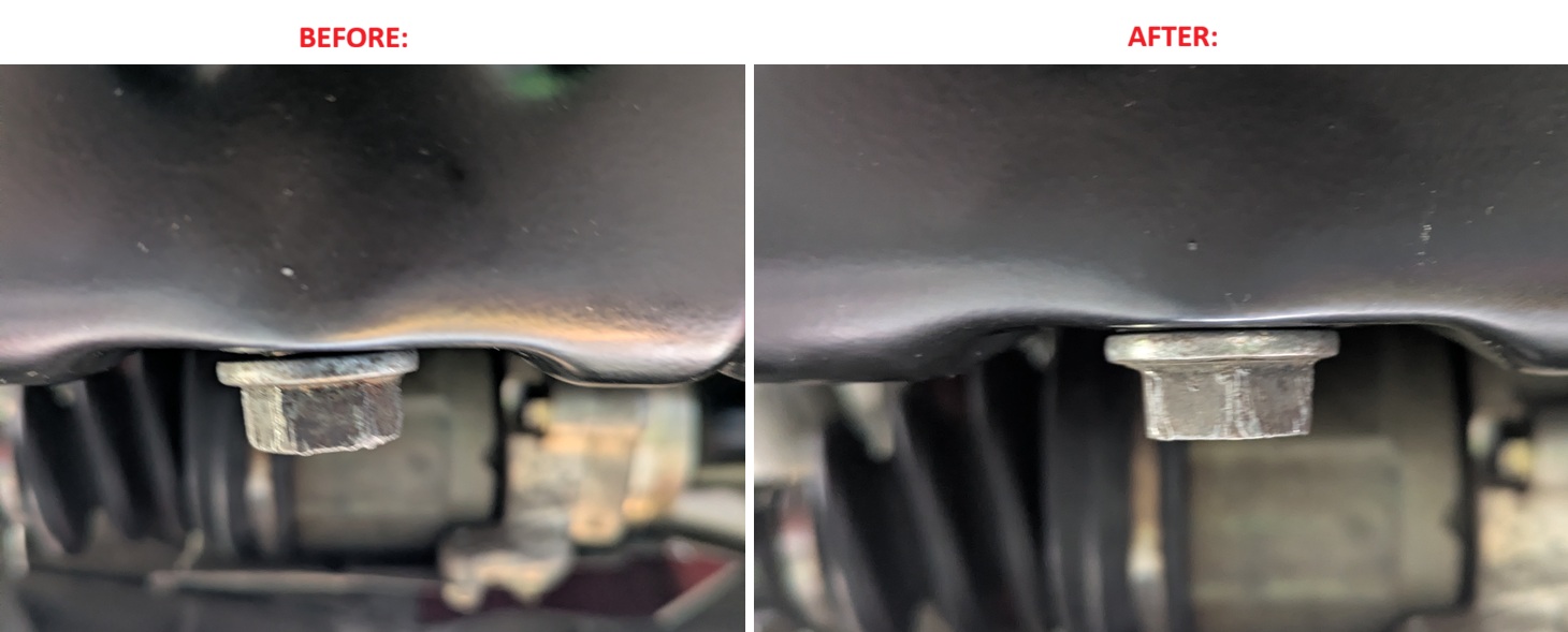
I'd expect anyone tackling this job would have basic tools (ie a socket set, torx bits, torque wrenches etc...). This is just outlining some specialty tools
Overall this was a semi difficult project. I've been wrenching on cars for 20 years and still struggled at times. You are always leaning over something. The car is aluminum so your magnetic work light doesn't want to stick to anything. A majority of the time it would tip over and point at the wrong thing or straight into my eyes. The coolant hoses were a pain to cut off. Some of the struggles were due to previous people who worked on the car. Spending 3-4 hours removing the over tightened valve cover grommets made me want to track down the previous mechanic and shove his impact gun to you know where... My lower dip stick tube bolt (yes the tiny 10mm bolt) was rounded off. I tried all the usual tricks... vice grips, an extractor, tapping on an undersized 12 point socket. I had to tack weld a wrench to it to break it free. I ended up breaking a knock sensor just trying to unplug it. RTV was used everywhere. Not only did it make removing some objects like the oil pan difficult, but it also was time consuming cleaning up all the residue.
My car also had the wrong coolant in it. Whoever did the water pump last used green coolant instead of blue. I opted to flush the system. Before turning off your car to begin the maintenance you should turn the heat on high which will open up the valve to the heater core. This will help everything drain. In addition to the normal draining process, the last coolant hoses I changed were the 3 under the car. Before changing them I blew compressed air in all 3 pipes in both directions which helped flush out more of the green coolant. Then I didn't immediately put the blue coolant in. I decided to flush the system using distilled water. I filled up and bled the system using 5 gallons of distilled water. Then I let the car run and warm up a few different cycles before draining it and repeating the process with the correct blue coolant.
One thing not mentioned in the factory service manual is the depth of the cam and crank oil seal. On some cars they don't want you to drive in the seals too far as it could block an oil passage. On my car the crank seal was driven in slightly more than flush. It looks like there is a lip where that was probably in as far as it could go. The Cam seals were the same way. In a Youtube video I watched a guy was spacing the cam seals out slightly from as far as they would go in. In a post on NSXPrime I read to push them in to the back plate that way you know they are square. Driving them in all the way is how mine were before removing them so that is what I did. In reality we are splitting hairs over a 1mm distance. I just think if you use the backing lip as a stop, it ensures the seals will all be square.
Before you pull the timing belt everything should be at TDCD. You've got the cams pinned with 5mm dowels (I used some Allen keys). You will loosen up all the bolts that hold the retainer plates and cam caps in. On the front head none of the cam lobes are fighting you so you may actually have to pry the caps up. On the rear head, the #3 and maybe #5 cylinder have some lobes pointing downward so as you loosen the bolts the caps will start to pop up. You should pull the cams with the cam gears still attached. Then use an impact gun to remove the cam gears afterwards. When you reinstall everything, leave the cam gears off. Make sure the dowel pin notches of the cam gears are facing up as that is how they were in the TDCD position. You'll have to set the camshafts in place with the cam seals already slid on part way. Then pickup the other end to slide the plugs in place. This is where you can eyeball and initially align the cam seals. Then make sure you have the hollow dowel pin in the head with the new O-ring installed. Make sure you cleaned and applied HondaBond to the right places (under outer cam caps near cam gear seals and cam plugs). Then set the caps and retainer plate on top.
Pin the cams as we need to keep them in the TDCD position as we tighten them down from a hovering position. This is easy on the front head, but more challenging on the rear head. This is where the factory service manual makes some sense. It wanted you to loosen all the valve adjustment nuts and back them off. This way there is no fight. A lot of people skip this (including myself). My car has low miles and I figured my valve adjustments are near perfect for me to want to mess with them. Looking back, I think there is a middle ground area. I bet if I would have just loosened the intake #3 and exhaust #5 valves the rear would have been easier. Just back off the valves where the lobes in TDCD face downward. Regardless as you tighten the bolts down (do it evenly) things will fall into place. Just before the cam caps make contact with the head, inspect the cam seals one last time. Make sure they are in. I used a short 1/4" extension to lightly push against the face of them to make sure they were fully seated. The manual wants you to apply oil to the threads and follow a torque sequence. So I kept tightening evenly until the caps make contact with the head. Then I pulled one bolt at a time, applied oil, re-inserted them, and snugged them lightly with a 1/4" ratchet to about where they were before. Then when all the bolts were in, I went through the torque sequence. The first run was just with the 1/4" ratchet again making them slightly tighter. Then I used a torque wrench. I opted not to apply oil ahead of time as I feared it could run out into the HondaBond on the outer cam caps as things were floating. By waiting until everything was pulled together, but not torqued... there would be no gap for any oil to run out. I suppose you could oil the threads on all the center bolts up front and do the one at a time method on just the outer cap bolts.
The other tip I have is installing the new belt. Assuming you have everything marked and start from the crank gear, the last thing it wants you to advance the rear most cam gear half a tooth and then slide the timing belt over it. I don't know about you, but sliding a toothed belt onto a toothed gear (the hardest gear to reach if I may add) is not an easy task. There are a lot of friction points where stuff can catch. So I slid the timing belt off the tensioner pulley instead. I got the belt on the rear cam gear where it should be and then I slid the belt back on the tensioner pulley. Then you can attach the spring and work through the tension points.